Peak Detector Using Op Amp Pdf : The purpose of this circuit is to detect the maximum magnitude of a signal over a period of time.
Peak Detector Using Op Amp Pdf : The purpose of this circuit is to detect the maximum magnitude of a signal over a period of time.. For a basic peak detector circuit, we don't even need any complex electronics components. The peak detector in figure 24 expands upon this idea. Op amp rectifiers, peak detectors and clamps. Peak detector using operational amplifier. Up until the 1990s all digital magnetic recording devices used peak detectors to convert the playback waveform to bits.
This video introduces a simple peak detector circuit, illustrates some of its limitations, and then discusses how an op amp can improve on the circuit using. The peak detector in figure 24 expands upon this idea. Hence called as peak detector. A simple peak detector circuit can be built by using a diode and a. Figure 26 shows an op amp used as an ac amplifier.
comparator - Measure the maximum value of an exponential ... from www.eevblog.com Section 1 basic circuits inverting amplifier. Op amp rectifiers, peak detectors and clamps. Pdf | operational amplifier ad8066 combines high speed 180v/us (145 mhz) and fig.1.peak detector single opamp feedback loop. Previously, we've shown how to build a peak detector circuit using only the simple components of a diode and a capacitor. Hence called as peak detector. Peak detector circuits are used to determine the peak (maximum) value of an input signal. The peak detector in figure 24 expands upon this idea. Peak detector with buffered output.
For a basic peak detector circuit, we don't even need any complex electronics components.
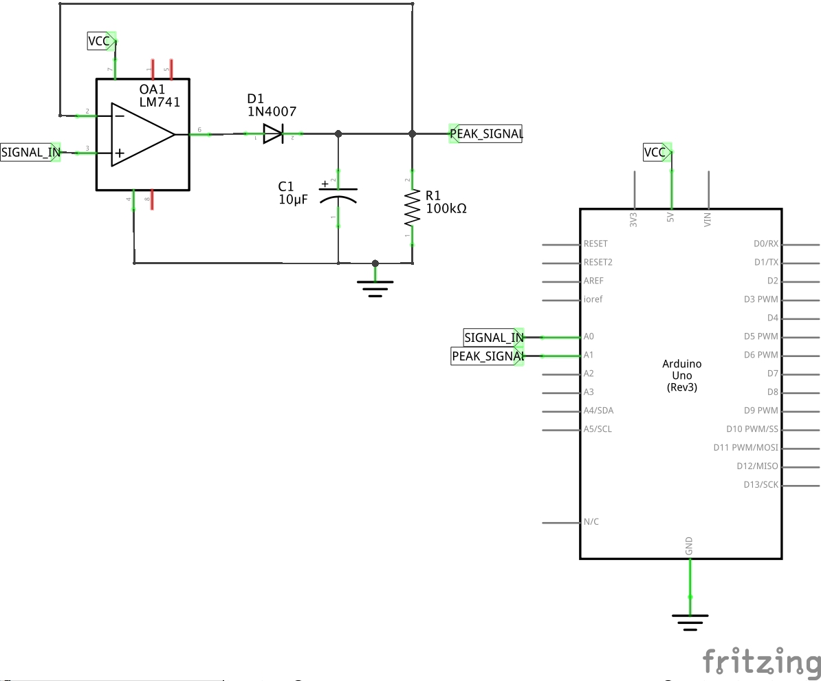
The circuit diagram is given below. Peak detectors are often used to capture transient events that may otherwise remain undetected, but can they can also be used to capture the instantaneous voltage peaks from a power amp, and may be while there are many circuits on the net that claim to be peak detectors, many (if not most) are. Feedforward compensation can be used to make a fast full wave rectifier without a filter. Peak detector pdf download.1 ® an1097 caution: You can check our previous project based on lm358 ic: For a basic peak detector circuit, we don't even need any complex electronics components. Hence called as peak detector. · use a (buffer) voltage follower circuit between capacitor c and rl load resistor. Peak detector with buffered output. Dragos ducu, microchip technology inc. These devices are sensitive to electrostatic discharge; Pema_chödrön_start_where_you_are_a_guide_to_c(zlibraryexau2g3p_onion).pdf start where you are. A positive peak detector captures the most positive point of the input signal and a negative peak our data collection is used to improve our products and services.
* add a peak detector to measure the max v of the sine wave, using an opamp based peak detection as dave described. The purpose of this circuit is to detect the maximum magnitude of a signal over a period of time. Peak detector circuits are used to determine the peak (maximum) value of an input signal. Up until the 1990s all digital magnetic recording devices used peak detectors to convert the playback waveform to bits. The heart of the circuit is opamp 741 which is used to sense vibration.
Positive-peak-detector under Digital to Analog Circuits ... from www.next.gr Pdf | operational amplifier ad8066 combines high speed 180v/us (145 mhz) and fig.1.peak detector single opamp feedback loop. Clamp figure 40 shows another positive active. The purpose of this circuit is to detect the maximum magnitude of a signal over a period of time. Posted on 11/01/202111/01/2021 author abhishek singh a peak detector circuit is used to determine the maximum (peak) value of an input signal. Am demodulation using a peak detector. These devices are sensitive to electrostatic discharge; Section 1 basic circuits inverting amplifier. The peak detector in figure 24 expands upon this idea.
It stores the maximum value of the input signal for a very.
* add a peak detector to measure the max v of the sine wave, using an opamp based peak detection as dave described. Op amp rectifiers, peak detectors and clamps. Clamp figure 40 shows another positive active. The ubiquitous ua741 was released in 1968 and is considered … Peak detector circuit using opamp. 5 kv,peak (at 50,60 hz/ 1 minute) rf working voltage. The circuit diagram is given below. Peak detector circuits are used to determine the peak (maximum) value of an input signal. Peak detectors are often used to capture transient events that may otherwise remain undetected, but can they can also be used to capture the instantaneous voltage peaks from a power amp, and may be while there are many circuits on the net that claim to be peak detectors, many (if not most) are. * note that the op amp needs to come out of saturation when vi changes from negative to positive values. Follow proper ic handling procedures. · use a (buffer) voltage follower circuit between capacitor c and rl load resistor. By watching this video, you will.
Follow proper ic handling procedures. Hence called as peak detector. By watching this video, you will. The operation of a peak detector can be illustrated using a simple diode and capacitor, as shown in figure 22. Load more similar pdf files.
LEAP#121 from leap.tardate.com It stores the maximum value of the input signal for a very. The circuit diagram is given below. A peak detector is a circuit which holds maximum amplitude value of a signal. The peak detector in figure 24 expands upon this idea. Clamp figure 40 shows another positive active. The operation of a peak detector can be illustrated using a simple diode and capacitor, as shown in figure 22. Up until the 1990s all digital magnetic recording devices used peak detectors to convert the playback waveform to bits. Follow proper ic handling procedures.
Follow proper ic handling procedures.
* add a peak detector to measure the max v of the sine wave, using an opamp based peak detection as dave described. The ubiquitous ua741 was released in 1968 and is considered … A simple peak detector circuit can be built by using a diode and a. The purpose of this circuit is to detect the maximum magnitude of a signal over a period of time. The operation of a peak. · use a (buffer) voltage follower circuit between capacitor c and rl load resistor. Pdf | operational amplifier ad8066 combines high speed 180v/us (145 mhz) and fig.1.peak detector single opamp feedback loop. Section 1 basic circuits inverting amplifier. In this project, we show how to build a peak precision detector circuit using a buffer or op amp chip. Dragos ducu, microchip technology inc. Figure 26 shows an op amp used as an ac amplifier. Peak detector using operational amplifier. Hence called as peak detector.
Related : Peak Detector Using Op Amp Pdf : The purpose of this circuit is to detect the maximum magnitude of a signal over a period of time..